Operating three stepper motors (DIR and PWM)

Hi all,
For our robot arm project, we need to power three 24V stepper motor using the CORE2-ROS.
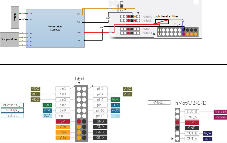
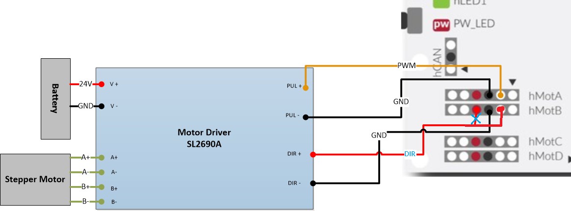
The drivers used are 2x SL2690A and one TB6600. Currently, we control 2 motors by using the following schematic for one motor driver (so HmotC and D are also in use) (thanks to the help of:Stepper motor wiring).

At the moment we are struggling with two types of issues, hopefully somebody can prove us insight into the following issues:

• With the current schematics for operating 2 motors(see schematic above) how can we code the directional signal so that we can give a logic high (5v +) signal or give a low signal (GND) so that it operates in opposite direction?
• Within the manual → Electrical specification → there is stated that there are “ 3.3v/5v tolerant GPIOs” would it be a possibility to use of the Hext pins (1-5) with GPIO function in order to give the stepper drives an DIR signal, so that each stepper motor only uses 1 Hmot (a,b,c,d) port, so that the total of 3 stepper motors can be powered (using 3 different Hmot ports)?

Thanks for your time!

Kind regards,
ARVI

Hi!

  1. Logic high or low can be set by manipulating the output power. You need the following command:

hMot1.setPower(power);

And there are 3 cases:
power=0 → both H-bridge outputs (OUTA, OUTB) will be at the low level (0V)
power>0 (eg. power=1000) → OUTA will be low, OUTB will be high (or PWM with duty cycle proportional to “power”)
power<0 (eg. power=-1000) → OUTA will be high (or PWM with duty cycle proportional to “power”), OUTB will be low

  1. The statement “3.3V/5V tolerant GPIOs” means that these GPIO can tolerate 5V signal on the input without damage. It does not mean that it can provide the 5V logic signal. However, it is worth checking if the 3.3V level is enough to drive the DIR signal. If not, you can use an additional level shifter circuit.
1 Like

Hi Radeknh,

Thanks for your time and reply.
3.3V level is not enough to drive the DIR signal, i will use an Bi-Directional Logic Level Converter in order to shift it to 5V. The following schematic is to control 1 stepper motor.


Using the following approach we can use 3 Hmotor ports in order to power the three stepper motors.