[Closed] Additional GPS and IMU sensor (ROSbot 2.0)

Hello.

I am trying to attach 2 additional GPS sensors and 1 additional IMU sensor to the Rosbot 2.0.

How can I publish GPS sensor data and IMU sensor data to ros topic?

Do I need to modify the firmware to get data from this sensor?

If I need to modify the firmware, which materialshould I refer?

Hi,
it mostly depends on the sensors you want to use. The easiest way is to connect the sensors via USB to ROSbot 2.0 Single Board Computer. Then you can make software on SBC.

What kind of sensors you want to use? Do you have datasheets of them?

Best regards,
Jakub Delicat

Hi!

I will use NEO-6M GPS 2ea and MPU-9250 1ea additionally.

I connect MPU-9250 on hSen2 and NEO-6M GPS in hSen4 and hSen5.

I follow assembly instruction for MPU-9250 connection in hSen2.

For two GPS sensors, I connect VCC-5V, GND-GND, RX-hSensX.pin3, and TX-hSensX.pin3, respectively.
The following figure shows the connection structure.

After that, maybe I have to add the library in lib file.
MPU9250 : MPU9250_Interface - interface imu mpu9250 | Mbed
NEO-6M GPS : GPS - read gps data | Mbed

What more do I need to do after adding the library?

Thank you!

Hi,
I forgot to ask earlier. Which ROS do you want to use?

Best regards,
Jakub Delicat

I use Ubuntu 18.04 + ROS melodic.

I edit rosbot-stm32-firmware to getting the motor pwm signal.

Hello @chokings

As Team Husarion, we will not be able to help you write dedicated code for a given sensor (unless in the form of an additional service). Are there any more ambiguities that need to be clarified so that you have a set of basic information to start work?

Best regards
Jan Brzyk

Okay, I understand.
If I want a software update that satisfies the above conditions, can I apply through the link below?

I try to make a firmware to use the additional sensors by myself.

I have a question about basic setting about Rosbot 2.0 core2.

In this robot, the hSens2 pins are empty as shown in figure below.

However, in the firmware code, SENS2_PIN3 and SENS2_PIN4 are defined by IMU_I2C_SCL and IMU_I2C_SDA like link below.

hSens2 was empty, but is it an unusable slot?

I am no sure if I understand this question. Can you elaborate?

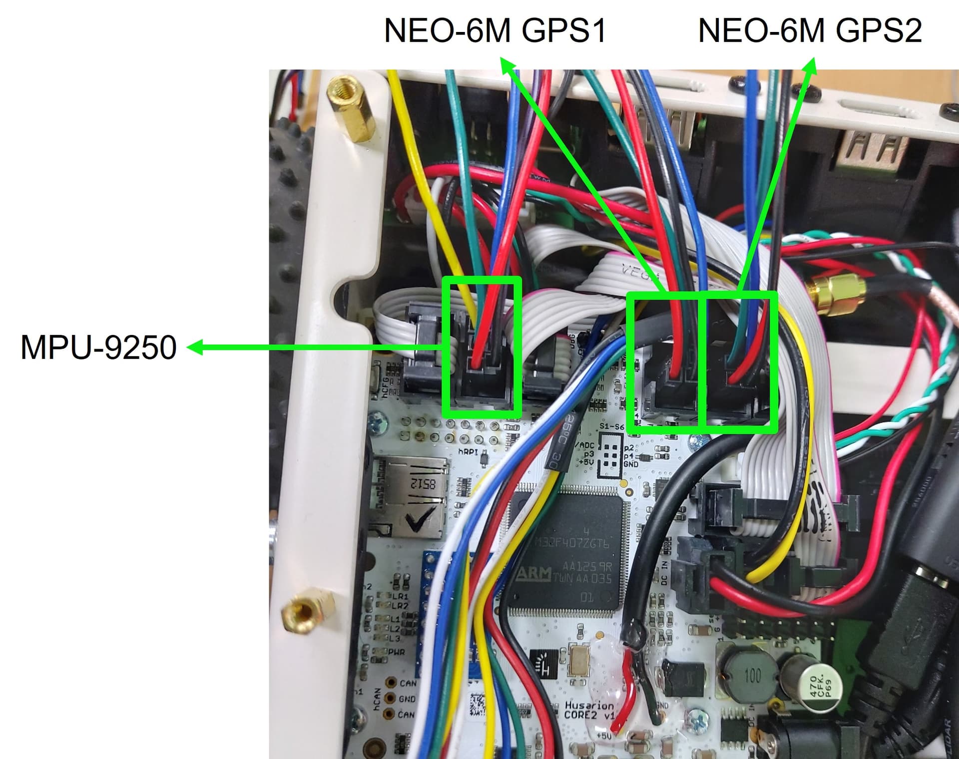
hSens2 connector shares GPIO/I2C pins with IMU (BNO055). In theory, I2C bus allows to add more devices and you could do it, but it needs more work in firmware. And we do not guarantee that IMU will still work good enough after that. Therefore, it is not recommended to use this port, unless you still want to use IMU. Also, the pin 2 of this connector is an output from IMU interrupt signal, so you cannot use this MCU pin as an output too.

There was a phrase Custom robot design in the link, so I asked if I could get the robot software that I wanted if I contacted them there.
But now I’m trying to fix the firmware myself.

thank you for the reply.
So, is it possible to attach additional IMUs to hExt?

Hi,
yes. This is possible. hExt interface is designed to connect the devices like MPU-9250 (I2C interface) or NEO-6M GPS (UART interface).

Thank you!

What about hSen5?
Are these pins connected to the LED as in the code comments below?

Hi.
We created this repository focusing on the “standard” peripherals of ROSbot 2(R) (PRO), which means that some interfaces are not included in the source code.
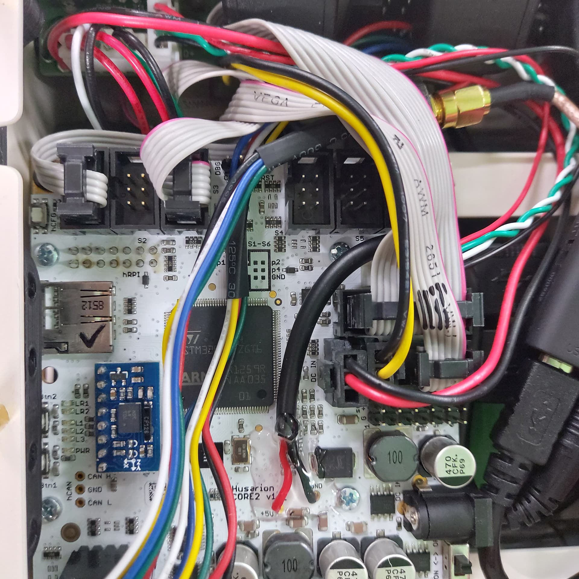
But you can write your own part of code, knowing which microcontroller pins are connected to the hSens5 and hExt ports. I prepared a cheatsheet for that purpose:


Remember that all hSens pins have the 660 ohm resistance in series, and all hExt pins have 330 ohm resistance in series.
I hope it helps.

2 Likes

I’m closing this thread after >2 months of inactivity.