Can you provide specifics how to use ST-Link to debug? I’ve never used a hardware debugger, how do you connect to the CORE2-ROS ?
Hello,
You need to connect ST-Link to debug port on CORE2 board, it is four pin connector between hSens ports. Some wire jumpers may be useful for connecting.
Install ST-Link driver, Windows should detect and install drivers automatically, on Linux you will need to follow this guide.
Open VSC and build project of your choice.
Press F9 to set breakpoint in place that you want to debug.
Press F5 to start debug session, keep pressing F5 to continue code execution after it stops at breakpoints.
Regards,
Łukasz
It worked perfectly, thanks! Very cool.
I’m trying to use ST-Link V2 to debug my CORE2 code but it is not working.
I have connected the four debug pins of the CORE2 to the 20 pins connector of the ST-Link programmer:
- Reset on pin 15
- SWDIO on pin 7
- GND on pin 20
- SWCLK on pin9
the programmer is correctly connected to the PC (it’s led is red).
When I press F5, there is the cmd prompt st-util.exe that flash the code.
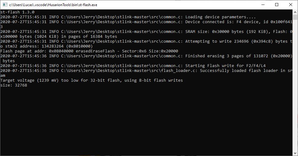
I don’t know if the Target voltage warning is a problem ?
After few seconds, the cmd prompt is like that:
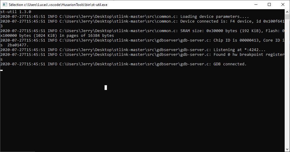
but the ST-LINK is orange (meaning target problem), and the debug console into VS code write
“ERROR: Warning:
Cannot insert hardware breakpoint 1.
Could not insert hardware breakpoints:
You may have requested too many hardware breakpoints/watchpoints.”
But there isn’t any breakpoint.
The debug tool doesn’t work at all (pause, breakpoints) and neither my code (that works fine with USB loader).
what did I forget?
Hi Baptiste,
May I ask you to try the same think with recommended ST desktop software. Please check also this tutorial. Note that this tutorial contain bootloader for project based on hFramework. Please let me know the results.
Best regards,
Hubert
Hi Hubert,
I tried with the STM32 ST-LINK Utility but it can’t connect to target. The tool ask me to try with “Connect Under Reset” option, I tried but there is no more effect.
I read your tutorial but I don’t see anything new or mistake from me.
I tryed to reflash the bootloader using this tutorial:
it works well like that.
So it seems that it’s the STLink can’t communicate at all with the MCU, why ?
Hi,
- Have you updated ST-LINK firmware to the newest version? You can do that in ST-LINK Utility, secelcting ST-LINK → Firmware update. ST-LINK should be connected via USB to proceed.
- Please try different Reset Mode Settings in the Target → Settings menu.
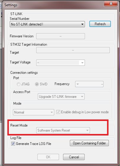
This is to verify if your CORE2 board is a problem or just the configuration.
Yes I have updated the ST-LINK firmware with the last version.
And yes I tried the tree reset mode options without any positive effect.
I also tried with another Core2 board so I think it’s really a configuration problem but I really don’t know where…
Some things, maybe obvious:
- Are you sure your board is powered through DC IN barrel connector when you try to flash CORE2, and the PWR LED is on?
- Try with lowered connection frequency.
- Try to disconnect RESET pin, leaving connected SWDIO, GND and SWCLK only - it may work with software reset.
- Try to hold RESET button before you try to connect with the target, then release and see what happens (with two configurations - RESET pin connected and not connected)
You may also share the log from some of your experiments with ST-LINK utility.
Sorry for the long delay.
Yes my board is powered from the DC connector with a stabilized power supply.
I tried with different frequency without any improvement. I checked with a 2 way oscilloscope the CLK and SWIO data and all seems coherent, there is a good clock and some data on the other way.
I tried to disconnect Reset pin and to hold reset button without any benefits.
There is almost nothing into the ST-LINK utility log file:
11:28:18 : Can not connect to target!
Please select “Connect Under Reset” mode from Target->Settings menu and try again.
If you’re trying to connect to a low frequency application , please select a lower SWD Frequency mode from Target->Settings menu.
11:28:22 : No target connected
11:29:01 : Can not connect to target!
Please select “Connect Under Reset” mode from Target->Settings menu and try again.
If you’re trying to connect to a low frequency application , please select a lower SWD Frequency mode from Target->Settings menu.
11:29:05 : No target connected
Hi Baptiste,
We used to use little a bit different ST-Link programmer, so we decide to buy and try the same one as yours.
It should be in our office tomorrow, so please let us some time to try it.
Best regards,
Hubert
It turns out that ST-LINK/V2 needs to check the target voltage before it can work. It is quite smart, thanks to that function you can avoid any damage of the target system when you use the same programmer with different systems. To check the target MCU supply voltage, the pin number 1 or 2 of 20-pin connector is used.
In case of CORE2 there is no 3.3V pin available to connect this “target voltage probe”. There are 3 options:
- Solder a wire to CORE2 board, to have 3V3 available (not very convenient).
- Make a voltage divider to achieve 3.3V from 5V, which is available on CORE2 (also not very easy).
- Cheat the ST-LINK/V2 programmer, making the connection between pins 1 and 19. See the picture below:
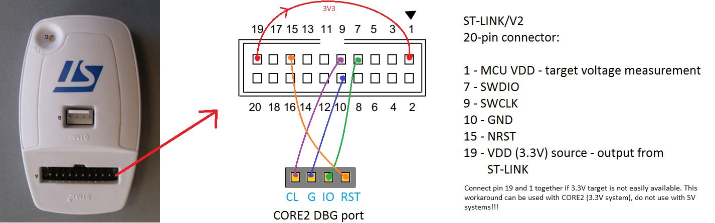
I hope it will work now. In case of CORE2 it is completely safe, both for CORE2 and ST-LINK/V2.
Yes it works, that was the problem. It’s really useful to be able to debug …
1 Like