We are planning to attach an additional device to the robot and safely power it from the onboard power board through CON8. Hence we have the following questions.
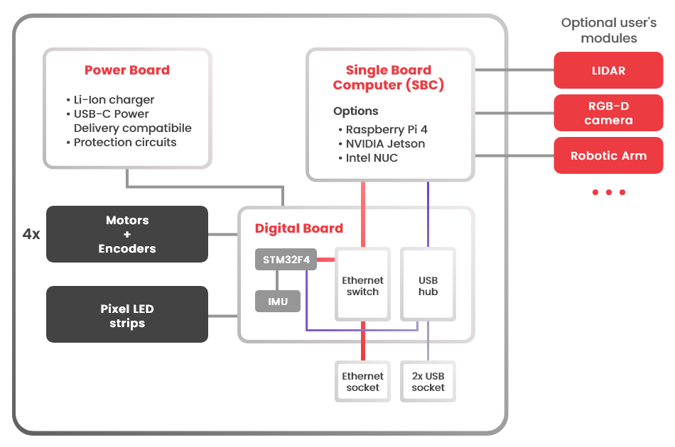
The Block diagram shows that the digital board (the MCU), but not the SBC, is connected to the power board to draw power from (not sure). Could you please confirm if this is really the case and where is the SBC getting power from? We have the impression that the SBC is getting power from the power board while the digital board is getting power from the SBC. Please confirm. By the way, our rosbot XL has Intel NUC.
The NUC specs says current required is 4.74A at 19V. However, in your website it says SBC supply port (CON9) has max current of 3A only for 19V. Do you have data as to how much current the whole system is drawing? It’s quite tricky to get these ourselves I guess. We were just wondering as well if it’s the 4.74A based from NUCs specs, then we could be in trouble in the long term if only 3A is the max output current.
We want to know the actual current drawn by the whole system so we can determine if the max current output of the power board which is 3A is enough for our application. This is considering that CON8 and CON9 are connected.
We know that we can just use an external power supply but we’re trying our luck with powering it via the power board.
Thank you for your detailed questions. I tried to split it into topics and answer each separately:
In the ROSbot XL configuration with Intel NUC:
The Intel NUC (SBC) is powered directly from the power board via CON9 (19V).
The digital board (MCU) is powered independently from the power board (not from the SBC).
The SBC does not supply power to the digital board.
So to confirm: the NUC is powered from the power board, and the MCU board is also powered from the power board via a separate power path.
The Intel NUC datasheet specifies 19V, up to 4.74A. This value represents maximum possible peak current, typically under heavy computational load and with external USB/peripheral devices attached.
In the ROSbot XL CON9 provides 19V with up to 3A continuous current. The system is designed to handle short transient spikes. However, typical continuous current draw of the NUC during standard robotic workloads is significantly below 3A.
CON8 and CON9 share the same 19V / 3A power rail
The 3A limit is shared between both connectors combined: Since your NUC is already connected to CON9, we do not recommend using CON8 simultaneously, as this could exceed the continuous current capability of the 19V rail in the long term.
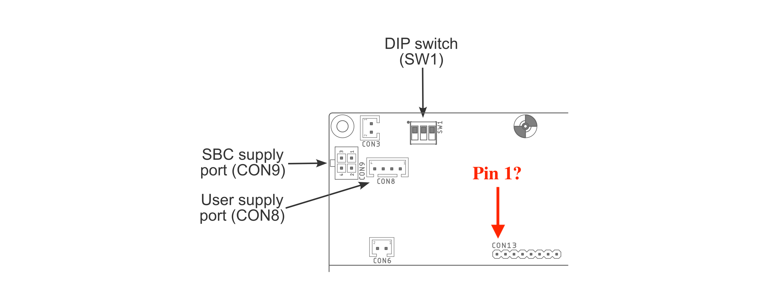
If you need to power an additional device, you may consider CON13 on the ROSbot XL power board.
CON13 pinout:
Pins 1-4: GND
Pin 5: Digital RA_Enable
Pins 6-8: VCC (battery voltage)
Important notes:
VCC = raw battery voltage (approximately 9V-12V)
This is unstabilized battery voltage.
It is protected by a 10A overcurrent protection shared with the robot motors, leaving you safely more than 5A.
If you decide to use CON13, proper safety mechanisms, voltage regulation and current management will be required on your side.
This is the same interface used in our manipulation package (RosBOT XL Robotic arm add-on), where voltage stabilization is implemented.
It took me a while to get back to this but I was just wondering if you would know the typical current draw of the NUC during standard operation which you said is significantly 3A. We’re thinking of just using CON8. Our additional device would have a current draw of ~1.5A.
Also, to clarify - the motors’ current drawn are separate from CON8 and CON9?
Yes, the motors are not connected to this converter and have independent power sources.
Unfortunately, I can’t answer how much current the NUC draws. It depends a lot on how heavily it’s loaded. From Intel NUC 13 Pro Mini PC Running Linux: Power Consumption article, I see NUC13 CPU usage from 22W (full CPU load at power save mode) upto 77W (full CPU load at performance mode)
Hi @Dhon_G,
The diagram You provided is correct Pin 5: Digital RA_Enable: Should work as a “Enable” indicator, meaning:
Pin 5 low: CON13 power not ready
Pin 5 High(3V3): CON13 power ready - can turn ON connected device
Pin 5 is digitally controlled by PowerBoard MCU and is one of the last steps in the bootup procedure.
Can you please confirm if EXT1 and EXT2 GPIOs are 5-V-tolerant as digital inputs?
I checked the datasheet and it says almost all of its I/Os are such. Just want to confirm if this is correct and if I am reading the correct datasheet.
The datasheet of STM32F407 on RosBOT XL Digital Board shows that the pins:
EXT_GPIO1 < - > PG2
EXT_GPIO2 < - > PG3
EXT_GPIO3 < - > PG4
Are 5V tolerant as Digital Input only.
Regards,
Tomas