Hi,
I am running the Rosbot2.0 with the new default firmware, and want to run multiple robots and therefore run the nodes under namespaces. I removed the absolute paths from rosbot_ekf/params/ekf_params.yaml and from msgs_conversion to be able to run everything in a namespace. However, the odom position values published by the rosbot_ekf node are off. When I push i once in the teleop node, the robot moves approx. 0.5m forward. When running in the namespace, the published odom position for x is ± 0.12m. I have no idea what is the problem. rqt_graph and rqt_tf_tree look normal. I also tried changing imu_link to rosbot1/imu_link in msgs_conversion.cpp, but this didn’t change anything. What remapping am I missing?
ekf_params.yaml:
frequency: 20

sensor_timeout: 0.2

two_d_mode: false

# Use this parameter to provide an offset to the transform generated by ekf_localization_node. This can be used for
# future dating the transform, which is required for interaction with some other packages. Defaults to 0.0 if
# unspecified.
transform_time_offset: 0.0

# Use this parameter to provide specify how long the tf listener should wait for a transform to become available.
# Defaults to 0.0 if unspecified.
transform_timeout: 0.0

# If you're having trouble, try setting this to true, and then echo the /diagnostics_agg topic to see if the node is
# unhappy with any settings or data.
print_diagnostics: true

debug: false

# Defaults to "robot_localization_debug.txt" if unspecified. Please specify the full path.
debug_out_file: /path/to/debug/file.txt

# Whether to broadcast the transformation over the /tf topic. Defaults to true if unspecified.
publish_tf: true

# Whether to publish the acceleration state. Defaults to false if unspecified.
publish_acceleration: false

# REP-105 (http://www.ros.org/reps/rep-0105.html) specifies four principal coordinate frames: base_link, odom, map, and
# earth. base_link is the coordinate frame that is affixed to the robot. Both odom and map are world-fixed frames.
# The robot's position in the odom frame will drift over time, but is accurate in the short term and should be
# continuous. The odom frame is therefore the best frame for executing local motion plans. The map frame, like the odom
# frame, is a world-fixed coordinate frame, and while it contains the most globally accurate position estimate for your
# robot, it is subject to discrete jumps, e.g., due to the fusion of GPS data or a correction from a map-based
# localization node. The earth frame is used to relate multiple map frames by giving them a common reference frame.
# ekf_localization_node and ukf_localization_node are not concerned with the earth frame.
# Here is how to use the following settings:
# 1. Set the map_frame, odom_frame, and base_link frames to the appropriate frame names for your system.
#     1a. If your system does not have a map_frame, just remove it, and make sure "world_frame" is set to the value of
#         odom_frame.
# 2. If you are fusing continuous position data such as wheel encoder odometry, visual odometry, or IMU data, set
#   "world_frame" to your odom_frame value. This is the default behavior for robot_localization's state estimation nodes.
# 3. If you are fusing global absolute position data that is subject to discrete jumps (e.g., GPS or position updates
# from landmark observations) then:
#     3a. Set your "world_frame" to your map_frame value
#     3b. MAKE SURE something else is generating the odom->base_link transform. Note that this can even be another state
#         estimation node from robot_localization! However, that instance should *not* fuse the global data.
map_frame: map              # Defaults to "map" if unspecified
odom_frame: odom            # Defaults to "odom" if unspecified
base_link_frame: base_link  # Defaults to "base_link" if unspecified
world_frame: odom           # Defaults to the value of odom_frame if unspecified

# The filter accepts an arbitrary number of inputs from each input message type (nav_msgs/Odometry,
# geometry_msgs/PoseWithCovarianceStamped, geometry_msgs/TwistWithCovarianceStamped,
# sensor_msgs/Imu). To add an input, simply append the next number in the sequence to its "base" name, e.g., odom0,
# odom1, twist0, twist1, imu0, imu1, imu2, etc. The value should be the topic name. These parameters obviously have no
# default values, and must be specified.
odom0: odom/wheel

# Each sensor reading updates some or all of the filter's state. These options give you greater control over which
# values from each measurement are fed to the filter. For example, if you have an odometry message as input, but only
# want to use its Z position value, then set the entire vector to false, except for the third entry. The order of the
# values is x, y, z, roll, pitch, yaw, vx, vy, vz, vroll, vpitch, vyaw, ax, ay, az. Note that not some message types
# do not provide some of the state variables estimated by the filter. For example, a TwistWithCovarianceStamped message
# has no pose information, so the first six values would be meaningless in that case. Each vector defaults to all false
# if unspecified, effectively making this parameter required for each sensor.
odom0_config: [true,  true,  true,
               false, false, true,
               false, false, false,
               false, false, false,
               false, false, false]

# If you have high-frequency data or are running with a low frequency parameter value, then you may want to increase
# the size of the subscription queue so that more measurements are fused.
odom0_queue_size: 6

# [ADVANCED] Large messages in ROS can exhibit strange behavior when they arrive at a high frequency. This is a result
# of Nagle's algorithm. This option tells the ROS subscriber to use the tcpNoDelay option, which disables Nagle's
# algorithm.
odom0_nodelay: false

# [ADVANCED] When measuring one pose variable with two sensors, a situation can arise in which both sensors under-
# report their covariances. This can lead to the filter rapidly jumping back and forth between each measurement as they
# arrive. In these cases, it often makes sense to (a) correct the measurement covariances, or (b) if velocity is also
# measured by one of the sensors, let one sensor measure pose, and the other velocity. However, doing (a) or (b) isn't
# always feasible, and so we expose the differential parameter. When differential mode is enabled, all absolute pose
# data is converted to velocity data by differentiating the absolute pose measurements. These velocities are then
# integrated as usual. NOTE: this only applies to sensors that provide pose measurements; setting differential to true
# for twist measurements has no effect.
odom0_differential: false

# [ADVANCED] When the node starts, if this parameter is true, then the first measurement is treated as a "zero point"
# for all future measurements. While you can achieve the same effect with the differential paremeter, the key
# difference is that the relative parameter doesn't cause the measurement to be converted to a velocity before
# integrating it. If you simply want your measurements to start at 0 for a given sensor, set this to true.
odom0_relative: true

# [ADVANCED] If your data is subject to outliers, use these threshold settings, expressed as Mahalanobis distances, to
# control how far away from the current vehicle state a sensor measurement is permitted to be. Each defaults to
# numeric_limits<double>::max() if unspecified. It is strongly recommended that these parameters be removed if not
# required. Data is specified at the level of pose and twist variables, rather than for each variable in isolation.
# For messages that have both pose and twist data, the parameter specifies to which part of the message we are applying
# the thresholds.
#odom0_pose_rejection_threshold: 5
#odom0_twist_rejection_threshold: 1

# values is x, y, z, roll, pitch, yaw, vx, vy, vz, vroll, vpitch, vyaw, ax, ay, az
imu0: imu                     #-----------------------------------------
imu0_config: [false, false, false,
              false, false, true,
              false, false, false,
              false, false, true,
              false, false, false]
imu0_nodelay: false
imu0_differential: true
imu0_relative: true
imu0_queue_size: 4
imu0_pose_rejection_threshold: 0.8                 # Note the difference in parameter names
imu0_twist_rejection_threshold: 0.8                #
imu0_linear_acceleration_rejection_threshold: 0.8  #

# [ADVANCED] Some IMUs automatically remove acceleration due to gravity, and others don't. If yours doesn't, please set
# this to true, and *make sure* your data conforms to REP-103, specifically, that the data is in ENU frame.
imu0_remove_gravitational_acceleration: true

# [ADVANCED]  The EKF and UKF models follow a standard predict/correct cycle. During prediction, if there is no
# acceleration reference, the velocity at time t+1 is simply predicted to be the same as the velocity at time t. During
# correction, this predicted value is fused with the measured value to produce the new velocity estimate. This can be
# problematic, as the final velocity will effectively be a weighted average of the old velocity and the new one. When
# this velocity is the integrated into a new pose, the result can be sluggish covergence. This effect is especially
# noticeable with LIDAR data during rotations. To get around it, users can try inflating the process_noise_covariance
# for the velocity variable in question, or decrease the  variance of the variable in question in the measurement
# itself. In addition, users can also take advantage of the control command being issued to the robot at the time we
# make the prediction. If control is used, it will get converted into an acceleration term, which will be used during
# predicition. Note that if an acceleration measurement for the variable in question is available from one of the
# inputs, the control term will be ignored.
# Whether or not we use the control input during predicition. Defaults to false.
use_control: true
# Whether the input (assumed to be cmd_vel) is a geometry_msgs/Twist or geometry_msgs/TwistStamped message. Defaults to
# false.
stamped_control: false
# The last issued control command will be used in prediction for this period. Defaults to 0.2.
control_timeout: 0.2
# Which velocities are being controlled. Order is vx, vy, vz, vroll, vpitch, vyaw.
control_config: [true, false, false, false, false, true]
# Places limits on how large the acceleration term will be. Should match your robot's kinematics.
acceleration_limits: [1.3, 0.0, 0.0, 0.0, 0.0, 3.4]
# Acceleration and deceleration limits are not always the same for robots.
deceleration_limits: [1.3, 0.0, 0.0, 0.0, 0.0, 4.5]
# If your robot cannot instantaneously reach its acceleration limit, the permitted change can be controlled with these
# gains
acceleration_gains: [0.8, 0.0, 0.0, 0.0, 0.0, 0.9]
# If your robot cannot instantaneously reach its deceleration limit, the permitted change can be controlled with these
# gains
deceleration_gains: [1.0, 0.0, 0.0, 0.0, 0.0, 1.0]   #-----------------------------------------


# [ADVANCED] The process noise covariance matrix can be difficult to tune, and can vary for each application, so it is
# exposed as a configuration parameter. This matrix represents the noise we add to the total error after each
# prediction step. The better the omnidirectional motion model matches your system, the smaller these values can be.
# However, if users find that a given variable is slow to converge, one approach is to increase the
# process_noise_covariance diagonal value for the variable in question, which will cause the filter's predicted error
# to be larger, which will cause the filter to trust the incoming measurement more during correction. The values are
# ordered as x, y, z, roll, pitch, yaw, vx, vy, vz, vroll, vpitch, vyaw, ax, ay, az. Defaults to the matrix below if
# unspecified.
process_noise_covariance: [0.05, 0,    0,    0,    0,    0,    0,     0,     0,    0,    0,    0,    0,    0,    0,
                           0,    0.05, 0,    0,    0,    0,    0,     0,     0,    0,    0,    0,    0,    0,    0,
                           0,    0,    0.06, 0,    0,    0,    0,     0,     0,    0,    0,    0,    0,    0,    0,
                           0,    0,    0,    0.03, 0,    0,    0,     0,     0,    0,    0,    0,    0,    0,    0,
                           0,    0,    0,    0,    0.03, 0,    0,     0,     0,    0,    0,    0,    0,    0,    0,
                           0,    0,    0,    0,    0,    0.06, 0,     0,     0,    0,    0,    0,    0,    0,    0,
                           0,    0,    0,    0,    0,    0,    0.025, 0,     0,    0,    0,    0,    0,    0,    0,
                           0,    0,    0,    0,    0,    0,    0,     0.025, 0,    0,    0,    0,    0,    0,    0,
                           0,    0,    0,    0,    0,    0,    0,     0,     0.04, 0,    0,    0,    0,    0,    0,
                           0,    0,    0,    0,    0,    0,    0,     0,     0,    0.01, 0,    0,    0,    0,    0,
                           0,    0,    0,    0,    0,    0,    0,     0,     0,    0,    0.01, 0,    0,    0,    0,
                           0,    0,    0,    0,    0,    0,    0,     0,     0,    0,    0,    0.02, 0,    0,    0,
                           0,    0,    0,    0,    0,    0,    0,     0,     0,    0,    0,    0,    0.01, 0,    0,
                           0,    0,    0,    0,    0,    0,    0,     0,     0,    0,    0,    0,    0,    0.01, 0,
                           0,    0,    0,    0,    0,    0,    0,     0,     0,    0,    0,    0,    0,    0,    0.015]

# [ADVANCED] This represents the initial value for the state estimate error covariance matrix. Setting a diagonal
# value (variance) to a large value will result in rapid convergence for initial measurements of the variable in
# question. Users should take care not to use large values for variables that will not be measured directly. The values
# are ordered as x, y, z, roll, pitch, yaw, vx, vy, vz, vroll, vpitch, vyaw, ax, ay, az. Defaults to the matrix below
#if unspecified.
initial_estimate_covariance: [1e-9, 0,    0,    0,    0,    0,    0,    0,    0,    0,     0,     0,     0,    0,    0,
                              0,    1e-9, 0,    0,    0,    0,    0,    0,    0,    0,     0,     0,     0,    0,    0,
                              0,    0,    1e-9, 0,    0,    0,    0,    0,    0,    0,     0,     0,     0,    0,    0,
                              0,    0,    0,    1e-9, 0,    0,    0,    0,    0,    0,     0,     0,     0,    0,    0,
                              0,    0,    0,    0,    1e-9, 0,    0,    0,    0,    0,     0,     0,     0,    0,    0,
                              0,    0,    0,    0,    0,    1e-9, 0,    0,    0,    0,     0,     0,     0,    0,    0,
                              0,    0,    0,    0,    0,    0,    1e-9, 0,    0,    0,     0,     0,     0,    0,    0,
                              0,    0,    0,    0,    0,    0,    0,    1e-9, 0,    0,     0,     0,     0,    0,    0,
                              0,    0,    0,    0,    0,    0,    0,    0,    1e-9, 0,     0,     0,     0,    0,    0,
                              0,    0,    0,    0,    0,    0,    0,    0,    0,    1e-9,  0,     0,     0,    0,    0,
                              0,    0,    0,    0,    0,    0,    0,    0,    0,    0,     1e-9,  0,     0,    0,    0,
                              0,    0,    0,    0,    0,    0,    0,    0,    0,    0,     0,     1e-9,  0,    0,    0,
                              0,    0,    0,    0,    0,    0,    0,    0,    0,    0,     0,     0,     1e-9, 0,    0,
                              0,    0,    0,    0,    0,    0,    0,    0,    0,    0,     0,     0,     0,    1e-9, 0,
                              0,    0,    0,    0,    0,    0,    0,    0,    0,    0,     0,     0,     0,    0,    1e-9]
msgs_conversion.cpp:
#include "ros/ros.h"
#include "rosbot_ekf/Imu.h"
#include "geometry_msgs/PoseStamped.h"
#include "sensor_msgs/Imu.h"
#include "nav_msgs/Odometry.h"

#define ODOM_COV 0.005
#define IMU_ORIENTATION_COV 0.05
#define IMU_ANG_VEL_COV 0.1
#define IMU_LIN_ACCEL_COV 0.5
#define PI 3.1415
#define G_ACCEL 9.8066

ros::Publisher *odom_pub_ptr;
ros::Publisher *imu_pub_ptr;

void poseCallback(const geometry_msgs::PoseStamped &pose_msg)
{
  nav_msgs::Odometry odom_msg;

  odom_msg.pose.pose.orientation.x = pose_msg.pose.orientation.x;
  odom_msg.pose.pose.orientation.y = pose_msg.pose.orientation.y;
  odom_msg.pose.pose.orientation.z = pose_msg.pose.orientation.z;
  odom_msg.pose.pose.orientation.w = pose_msg.pose.orientation.w;

  odom_msg.pose.pose.position.x = pose_msg.pose.position.x;
  odom_msg.pose.pose.position.y = pose_msg.pose.position.y;
  odom_msg.pose.pose.position.z = pose_msg.pose.position.z;

  odom_msg.pose.covariance[0] = ODOM_COV;
  odom_msg.pose.covariance[7] = ODOM_COV;
  odom_msg.pose.covariance[14] = ODOM_COV;
  odom_msg.pose.covariance[21] = ODOM_COV;
  odom_msg.pose.covariance[28] = ODOM_COV;
  odom_msg.pose.covariance[35] = ODOM_COV;


  odom_msg.header = pose_msg.header;

  odom_pub_ptr->publish(odom_msg);

}

void mpuCallback(const rosbot_ekf::Imu &mpu_msg)
{
  sensor_msgs::Imu imu_msg;

  imu_msg.header = mpu_msg.header;
  imu_msg.header.frame_id = "imu_link";

  imu_msg.orientation.x = mpu_msg.orientation.x;
  imu_msg.orientation.y = mpu_msg.orientation.y;
  imu_msg.orientation.z = mpu_msg.orientation.z;
  imu_msg.orientation.w = mpu_msg.orientation.w;

  imu_msg.angular_velocity.x = mpu_msg.angular_velocity[0] * PI / 180;
  imu_msg.angular_velocity.y = mpu_msg.angular_velocity[1] * PI / 180;
  imu_msg.angular_velocity.z = mpu_msg.angular_velocity[2] * PI / 180;

  imu_msg.linear_acceleration.x = mpu_msg.linear_acceleration[0] * G_ACCEL;
  imu_msg.linear_acceleration.y = mpu_msg.linear_acceleration[1] * G_ACCEL;
  imu_msg.linear_acceleration.z = mpu_msg.linear_acceleration[2] * G_ACCEL;

  imu_msg.orientation_covariance[0] = IMU_ORIENTATION_COV;
  imu_msg.orientation_covariance[4] = IMU_ORIENTATION_COV;
  imu_msg.orientation_covariance[8] = IMU_ORIENTATION_COV;

  imu_msg.angular_velocity_covariance[0] = IMU_ANG_VEL_COV;
  imu_msg.angular_velocity_covariance[4] = IMU_ANG_VEL_COV;
  imu_msg.angular_velocity_covariance[8] = IMU_ANG_VEL_COV;

  imu_msg.linear_acceleration_covariance[0] = IMU_LIN_ACCEL_COV;
  imu_msg.linear_acceleration_covariance[4] = IMU_LIN_ACCEL_COV;
  imu_msg.linear_acceleration_covariance[8] = IMU_LIN_ACCEL_COV;


  imu_pub_ptr->publish(imu_msg);

}


int main(int argc, char **argv)
{

  ros::init(argc, argv, "msgs_conversion");


  ros::NodeHandle n;

  ros::Publisher imu_pub = n.advertise<sensor_msgs::Imu>("imu", 1);
  imu_pub_ptr = &imu_pub;
  ros::Publisher odom_pub = n.advertise<nav_msgs::Odometry>("odom/wheel", 1);
  odom_pub_ptr = &odom_pub;

  ros::Subscriber mpu_sub = n.subscribe("mpu9250", 1000, mpuCallback);
  ros::Subscriber pose_sub = n.subscribe("pose", 1000, poseCallback);

  ros::Rate loop_rate(20);

  while (ros::ok())
  {
    ros::spinOnce();
    loop_rate.sleep();

  }


  return 0;
}
Launch files for running in namespace:
Note: Serial bridge is not in namespace but all topics are remapped, because I didn’t want to change the firmware.
all_ns.launch
<launch>
    <arg name="rosbot_pro" default="false"/>
    <arg name="robot_name" default="rosbot1"/>
    <include unless="$(arg rosbot_pro)" file="$(find rosbot_ekf)/launch/rosserial_bridge_ns.$
    <arg name="robot_name" value="$(arg robot_name)"/>
    </include>

    <include if="$(arg rosbot_pro)" file="$(find rosbot_ekf)/launch/rosserial_bridge_ns.laun$
        <arg name="serial_port" value="/dev/ttyS4"/>
        <arg name="serial_baudrate" value="460800"/>
        <arg name="robot_name" value="$(arg robot_name)"/>
    </include>

    <include file="$(find rosbot_ekf)/launch/message_conversion_ns.launch">
        <arg name="robot_name" value="$(arg robot_name)"/>
    </include>

    <include file="$(find rosbot_ekf)/launch/rosbot_ekf_ns.launch">
        <arg name="robot_name" value="$(arg robot_name)"/>
    </include>
</launch>
rosserial_bridge_ns.launch
<launch>
  <arg name="serial_port" default="/dev/ttyS1"/>
  <arg name="serial_baudrate" default="500000"/>
  <arg name="robot_name" default="rosbot1"/>

  <node pkg="rosserial_python" type="serial_node.py" name="serial_node" output="screen">
    <param name="port" value="$(arg serial_port)"/>
    <param name="baud" value="$(arg serial_baudrate)"/>
     <remap from="cmd_vel" to="/$(arg robot_name)/cmd_vel"/>
            <remap from="range/fl" to="/$(arg robot_name)/range/fl"/>
            <remap from="range/fr" to="/$(arg robot_name)/range/fr"/>
            <remap from="range/rl" to="/$(arg robot_name)/range/rl"/>
            <remap from="range/rr" to="/$(arg robot_name)/range/rr"/>
            <remap from="pose" to="/$(arg robot_name)/pose"/>
            <remap from="velocity" to="/$(arg robot_name)/velocity"/>
            <remap from="mpu9250" to="/$(arg robot_name)/mpu9250"/>
            <remap from="joint_states" to="/$(arg robot_name)/joint_states"/>
            <remap from="battery" to="/$(arg robot_name)/battery"/>
            <remap from="buttons" to="/$(arg robot_name)/buttons"/>
  </node>
</launch>
message_conversion_ns.launch
<launch>
  <arg name="robot_name" default="rosbot1"/>
  <node ns="$(arg robot_name)" pkg="rosbot_ekf" type="msgs_conversion" name="msgs_conversion">
  </node>
</launch>
rosbot_ekf_ns.launch
<launch>
  <arg name="robot_name" default="rosbot1"/>
  <node ns="$(arg robot_name)" pkg="robot_localization" type="ekf_localization_node" name="rosbot_ekf">
    <rosparam command="load" file="$(find rosbot_ekf)/params/ekf_params.yaml" />
    <param name="tf_prefix" value="$(arg robot_name)"/>
   <!--  Placeholder for output topic remapping -->
    <remap from="odometry/filtered" to="odom"/>
    <!-- <remap from="accel/filtered" to=""/> -->

  </node>
</launch>
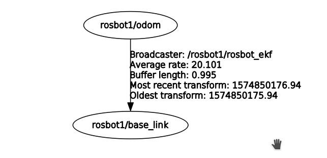
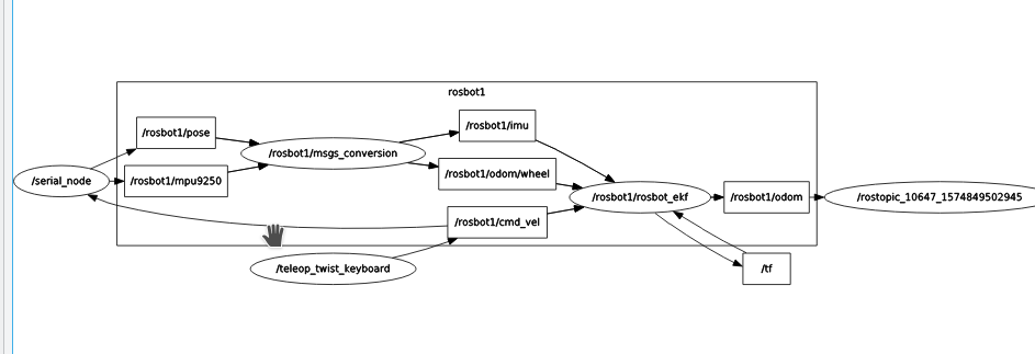
So concluding: Everything seems to be working normal but the extended kalman filter from rosbot_ekf gives very wrong output when running in a namespace.
Hopefully you could help me with this.
Thanks,
Xander

