Hi there,
I just want to confirm a few things about the Estop trigger input on the Panther:
-
to use the 3V to 12V signal, could I use the voltage (5V or 12V) as available on the user power panel in the inside compartment, and going through a relay (to trigger estop or not)? Are these voltage stable enough and not affected by the battery state of charge so it could be used for the estop function?
-
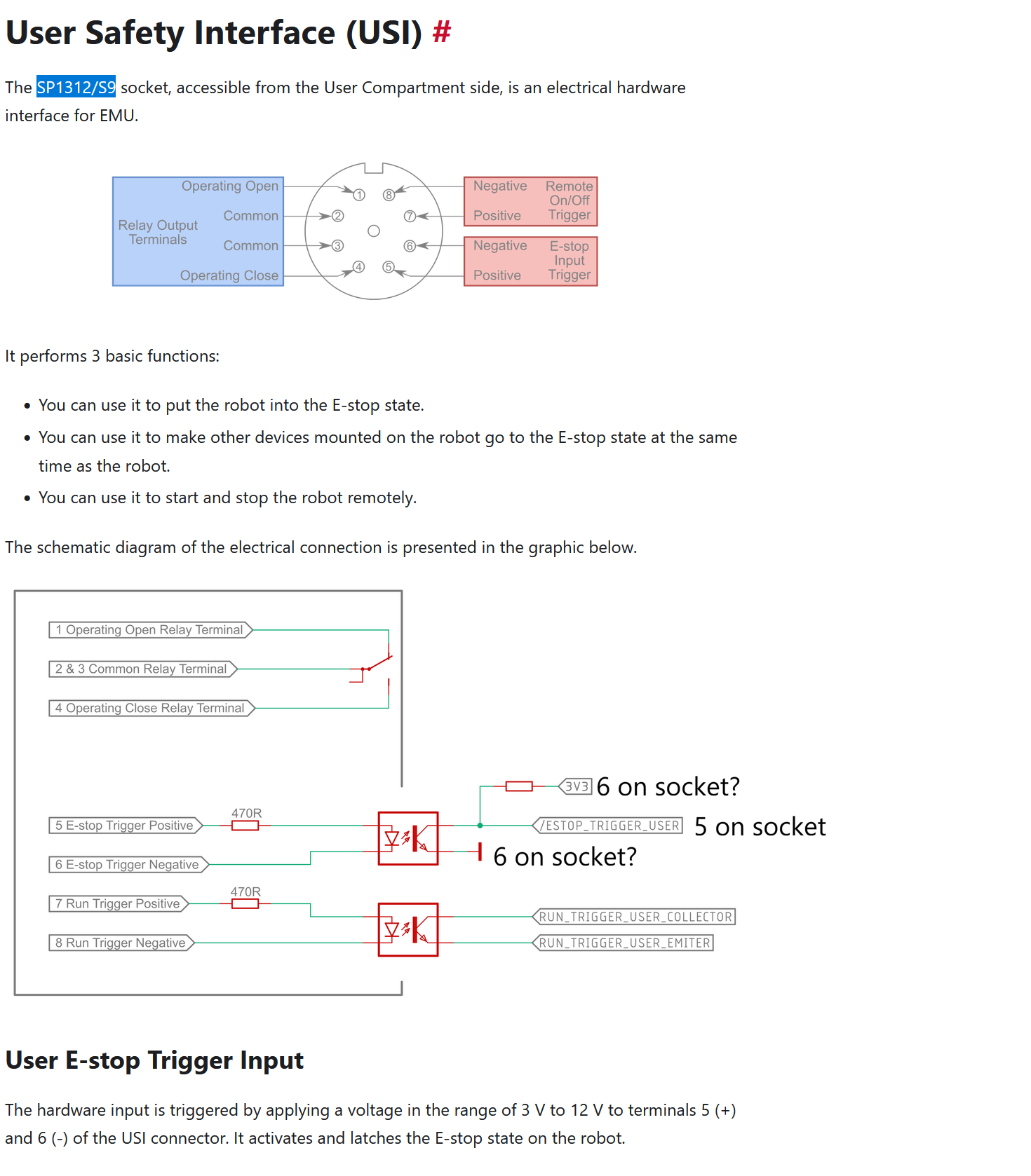
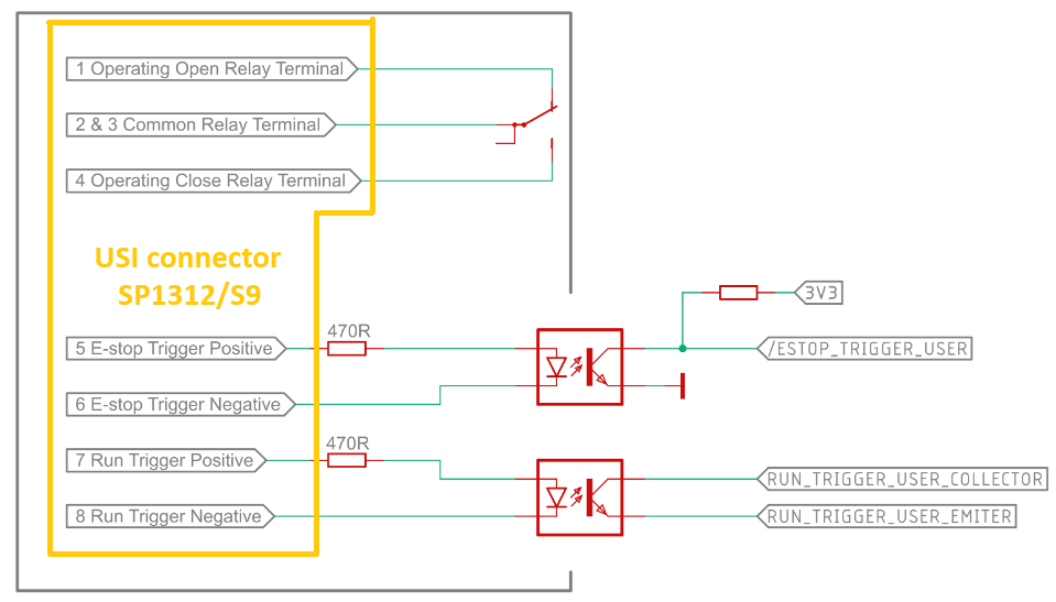
just want to confirm the pin description on the SP1312/S9 socket and the schematic diagram of electrical connection, confirming that on the user side we connect just the Estop_Trigger_User on pin 5 but what would be the pin 6 on socket (0V or 3.3V?). Out of curiosity what is resistor value on the 3.3V show on the schematics.
-
Do you have an online reference for the hardware that could be plugged onto the SP1312/S9 socket, especially that would be with flying leads (already soldered).
Thank you for your help,
Nicolas
Before I provide a definitive answer regarding the USI user Estop trigger interface, could you please confirm the Panther hardware version you are working with?
You can find the Hardware Version on the product label located in the User Compartment.
Hi,
the hardware version is 1.23b
Thank you very much,
Nicolas
Hi Nico,
-
Yes the UPP (User Power Panel) is appropriate to use to trigger Estop using USI.
-
USI socket SP1312/S9 pins are described on the left side of the diagram, where on the right you find Robots logic. To latch E-stop using USI interface you can provide 12V on pin 5 (E-stop Trigger Positive) and GND on pin 6 E-stop Trigger Negative.
-
The plug model, compatible with SP1312/S9 receptacle, is Weipu SP1310/P9. It is made to be soldered with wires.
Important info for Panther v1.30 or higher users: The E-stop trigger circuit was changed in Panther v1.30 and we are going to update our documentation in the following days. As for today, the online manual of USI circuit is correct only for version v1.23d and below. We apologize for inconvenience.
Hi,
thank you for your reply, I totally misread the schematics originally.
Just confirming one point: to use the 3V to 12V signal, could I use the voltage (5V or 12V) as available on the robot user power panel in the inside compartment, and going through a relay (to trigger Estop or not)? Are these voltage stable enough and not affected by the battery state of charge so it could be used for the estop function?
Is this estop USI trigger safety rated?
Thank you,
Nicolas
Hi,
thanks and great news for the incoming development. I would suggest that 0V should be triggering an Estop (opening an Estop circuit) and the 12V or 24V should be de-activating the Estop. A switch option should allow to activate the function or de-activate it, so if people want to use the Panther without the Estop being wired they could.
Thanks again,
Nicolas
1 Like