My panther robot will not power on. The battery is fully charged. The power switch lights up when it is turned to the on position.
Hi PFF.
Did you check if Panther’s WiFi is available after booting?
Also, could you provide me with serial number of your robot?
Best regards,
Krzysztof Wojciechowski.
Hello Krzysztof,
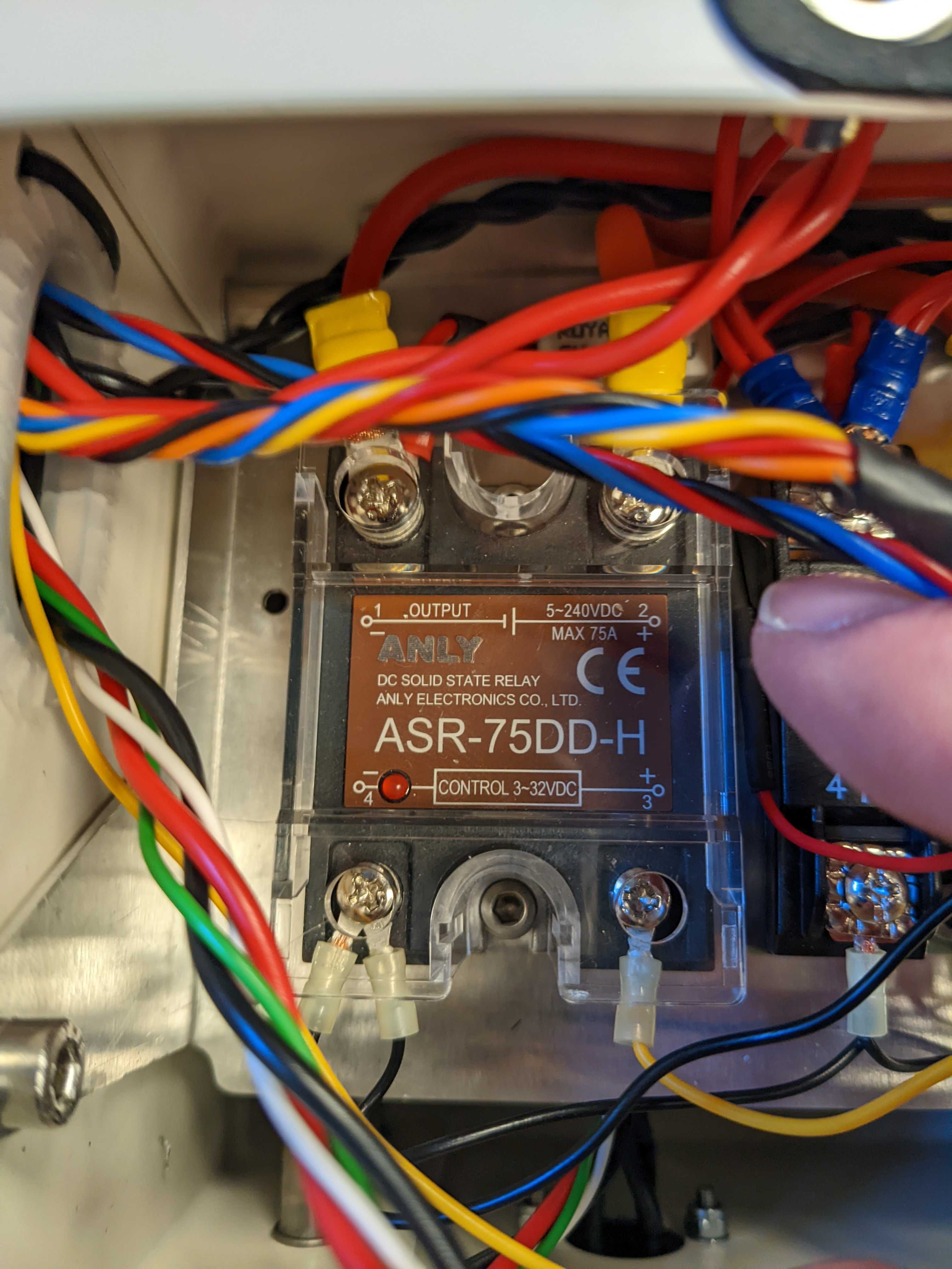
The serial number of the robot is 2559. On Friday the robot power and ran. Today the robot would not power on. I think I have debugged it to the Amly relay. With the power switch off, the voltage across the control pins is 0V. When the switch it turned to CPU, the voltage across the control pins is 27V, but the relay does not activate. The status LED does not turn on.
I have looked to source a replacement relay, but I can not find this relay in the US. Can you either rush send me one or give me specs for what the relay should be and I can find a cross?
Thanks,
Jason
I really appreciate your time spent on debugging.
The 27V you measured is the correct in case the switch is set to the CPU position. If you can and feel confident enough doing so, could you check the resistance between the following points described below?
First of all, perform all the tests with the switch in the Off position. Also note that the capacity in points you will be measuring might be large enough to distort the first few reading, so long measurement and double-checking would be nice. Places marked with a lightning bolt are under battery voltage, so also be careful with those.
Perform following checks:
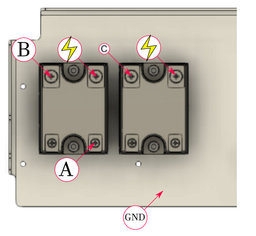
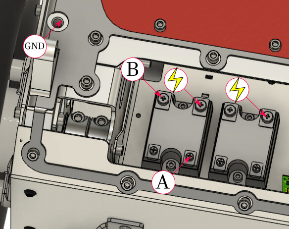
- measure the resistance between point A and the frame. The resistance should be 0 or close to 0 Ohm.
- measure resistance between points A and B. This one should be non-zero.
Those measurements will tell us if the relay is for sure broken, and also give us an insight into what potentially might’ve caused that.
Images below show where to find mentioned points.
Best regards,
Krzysztof Wojciechowski.
Hello Krzysztof,
My relay is wired a bit differently. See attached picture. The terminal you have unlabeled is GND. It is tied to the GND stud in the chassis. The relay also calls this the - terminal. The A terminal is the control signal. This wire is yellow and has the 27V from the switch on it. The lightning bolt is V_BATT at 42V, and B is the output which never changes. None of the terminals are shorted to each other.