I would like to read an incoming PWM signal with Core2, is this possible? On Arduino, you can use pulseIn or attachInterrupt and look for the signal rise Three Ways To Read A PWM Signal With Arduino | BenRipley.com
Hi,
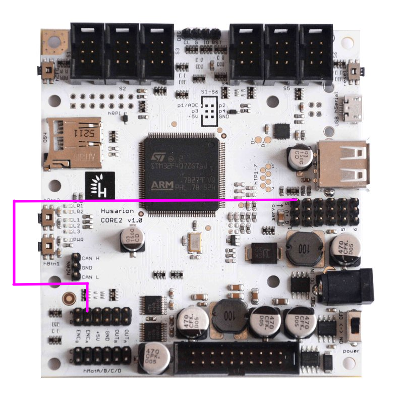
Sure it is possible. The CORE2 has STM32F40ZG uC equipped with timers capable of input capture functionality. However the best way to measure the pwm input period and duty cycle would be to configure one of the high resolution (32bit) timers like TIM2 to use ‘Pwm Input Mode’. This mode uses one channel as an input, pairs channel 1 and channel 2, and resets the counter allowing you to calculate the signal period and pulse width using TIM2_CCR1 and TIM2_CCR2 registers. The TIM2’s CH1 and CH2 pins are CORE2’s MOT1 (PA0) encoder A and MOT1 encoder B (PA1) pins respectively. To learn more check document RM0090 Section 18. General-purpose timers (TIM2 to TIM5).
The only problem is that hFramework doesn’t use the ST HAL libraries so you would have to write the driver yourself using registers. You might be interested using our Mbed-OS template for CORE2. Mbed-OS uses ST HAL to control STM32 targets’ peripherals so you can even use code generated with Stm32CubeMx.
If you want to I can create some example how to use this feature.
Yeah, I’ve never done any register programming, was hoping for a library. Any help you could offer would be appreciated!
Hi,
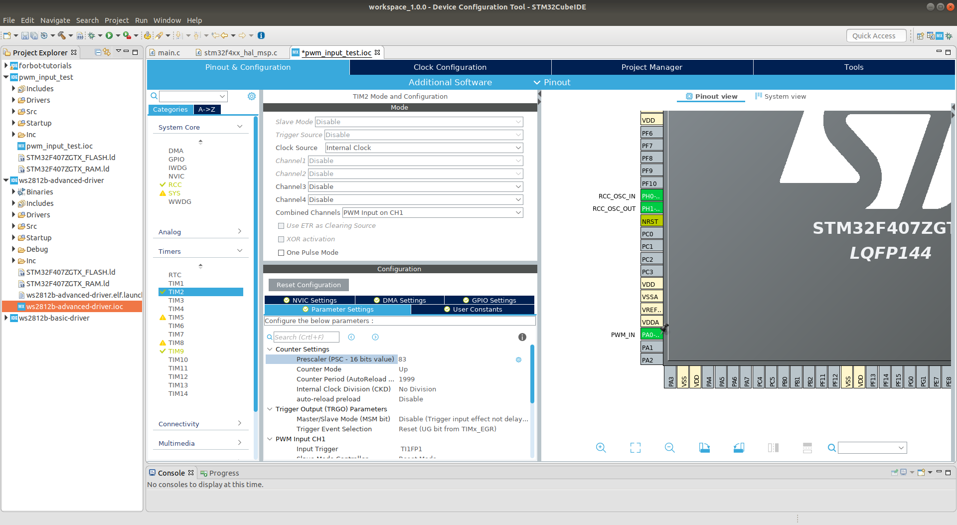
Here is the example. I configured TIM2 on pin PA_0 (MOT1 encoder A pin). I setup the timer with 2ms period (500Hz) and resolution of 2000 (the Auto Reload Register = 1999). As a test signal I used pwm on pin PE_9 (servo 1 pwm pin) with period 1ms (1000Hz) so it can be measured with the timer. This way we can measure the input pwm signal’s duty with 0.1% accuracy (input signal takes half of the timer period).
Connect the pins like that:
The code is written using mbed, so at the beginning you will need to set up your environment using our template:
All necessary steps are described in the README.
The code is here:
main.cpp (6.4 KB)
To get the timer configuration part I used STM32CubeMx tool from STM32Cube IDE and then copied generated config code to my mbed program.
In case you want to check the functionality now, here is the .hex file. You can upload it to your CORE2 using core2flasher tool.
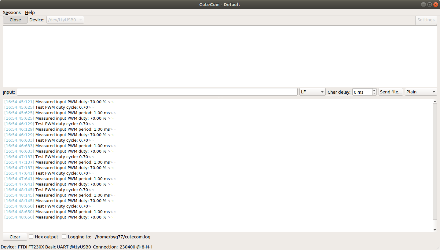
Use button 1 and button 2 to increase and decrease the test pwm duty cycle. Open serial monitor with baudrate 230400 to see measurement information:
I will try soon, but I still can’t compile locally No Member getRefTime - #11 by PureRockets