Hi,
Any chance you have any sample/tutorial for GPIO configuration and use in ROSbot XL?
I am under the impression that the firmware has to be modified to expose GPIOs and other pins.
Hi,
Any chance you have any sample/tutorial for GPIO configuration and use in ROSbot XL?
I am under the impression that the firmware has to be modified to expose GPIOs and other pins.
Hi @Dhon_G,
This type of issue is very uncommon, and we don’t currently have any recorded cases of it.
That said, we’re in the final stage of a firmware refactoring, which will be officially released soon. In the meantime, you can test the latest version on ROSbot by downloading the Snap package from the jazzy/edge channel: Install rosbot on Linux | Snap Store.
For your purpose, you can also make custom modifications directly in the firmware repository: GitHub - husarion/rosbot-firmware: Unified micro-ros based firmware for ROSbot 3 and ROSbot XL for STM32F4 microcontroller. · GitHub. The project structure is relatively straightforward, so implementing GPIO-related changes should be manageable.
The rosbot-firmware repository includes tasks for building the firmware. Once built, it can be flashed using the rosbot_ros repository and the following command:
ros2 run rosbot_utils flash_firmware --robot-model <rosbot/rosbot_xl>
-f <firmware>
If you encounter any difficulties, I will try to advise you.
Hi @RafalGorecki ,
Thanks, will give firmware modification a shot.
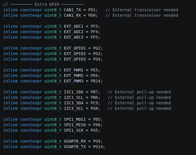
I’ll be using EXT_GPIO1, EXT_GPIO2, EXT_GPIO3, and EXT_PWM1.
@Tomasz_Lejkowski provided me the corresponding STM pins for the GPIOs as follows.
EXT_GPIO1 < - > PG2
EXT_GPIO2 < - > PG3
EXT_GPIO3 < - > PG4
Are you able to provide me the corresponding STM pin for the EXT_PWM1?
Hi @RafalGorecki ,
Do you mean you will write the code to expose these extra GPIOs and functionalities to ROS or just pin configs?
I’ve only added the STM32 pin names to the config. I can’t configure them because the configuration depends on how they’re to be used.
No worries. I tried to implement the extra GPIOs - GPIOs 1 & 2 and PWM1 as digital outputs while GPIO 3 as input. GPIO 3 will read from an encoder sensor and publish pulse count every 100ms. Are you able to review the code for me? I haven’t built or tested it yet as I’m too afraid to try. I have no experience updating a firmware before.
Here’s the link to the forked repo in case you’re open to checking: GitHub - dfavr24/rosbot-firmware: Unified micro-ros based firmware for ROSbot 3 and ROSbot XL for STM32F4 microcontroller. · GitHub
Regards,
Dhong
Unfortunately, I can’t verify the code’s accuracy.
Regarding flashing, the latest version of jazzy/edge adds the ability to replace the original firmware. You can replace default firmware file with your custom one.
Example:
cd /var/snap/rosbot/current/config_dir/rosbot_utils/firmware
mv rosbot-v1.0.1-jazzy.bin rosbot-v1.0.1-jazzy-backup.bin # Create buckup for rosbot firmware
cp /<path_to_firmware>/firmware.bin rosbot-v1.0.1-jazzy.bin
sudo rosbot.flash
No problem, thanks.
I was just wondering what would you recommend for debugging?
I managed to build and flash the edited firmware. When running micro ros agent, the topics successfully appear in the list however can’t get something to work in the actual hardware when trying to publish something in the topics.
Software Diagnostics
You can use debugSerial
You can monitor the debug output over USB. The device should appear with the following USB identifiers:
04036015Any serial terminal application can be used to read the logs, for example:
platformio device monitorminicomscreenpicocomSerial communication parameters:
9216008None1 (8-N-1 )Example using PlatformIO:
platformio device monitor -b 921600 -p <serial_port> # e.g. /dev/ttyUSB0
Hardware Diagnostics
It is also recommended to use a logic analyzer to verify whether the electrical signals on the bus match the expected values.
Hi,
Thanks.
I ended up using “screen” command to debug. I’ve also confirmed electrical output from the pins using a multimeter. It turned out there’s an error with my message handle definition and an issue with my motor driver.
Thanks for all the help. I guess we can move forward from here.
Regards,
Dhong
I’m glad I could help and good luck with your project
By the way @RafalGorecki, we found out after getting unexpected voltage levels that EXT2 PIN13 is not GND. We’re getting 3.3V from that pin. We had to use PIN1 for GND.
Hi @Dhon_G,
Can you confirm you haven’t mixed up the ports? There are two GPIO connectors on the board:
In EXT1, pin 13 is GND, while in EXT2, pin 13 is 3.3V.
Hi @RafalGorecki ,
That’s interesting! I sent you an email in support@husarion.com. Hope you have time to check it as it is important.
Thanks!
Hi @RafalGorecki ,
After testing, I realise that the “architecture” of the new firmware is different from the one which I built my ROS2 project from. I’m using last year’s version of rosbot_ros (forked 17 October 2025) which based on commit history is using the v1.4.0.bin firmware version with stm32_node. My question is, where do I find the code for that firmware version? Will the new firmware version work on that rosbot version with just a few tweaks?
Regards,
Dhong
I think I found it: GitHub - husarion/rosbot_xl_firmware: Micro-ROS powered fimware for ROSbot XL · GitHub
Let me explain.
In recent months, I’ve been unifying the ROSbot 3 and ROSbot XL firmware, as they shared many similar concepts. This resulted in the release of the newest and currently under development repository: rosbot-firmware
It is compatible with rosbot_ros versions 1.0.0 and newer.
rosbot_ros versions lower than 1.0.0 rely on two separate firmware repositories:
rosbot_ros2_firmware for ROSbot 3rosbot_xl_firmware for ROSbot XLAt the same time, work is still ongoing on the official distribution of the latest 1.0.0 release, and I strongly encourage using the newer version whenever possible.
Once everything is finalized, I plan to publish an article summarizing all the major changes and improvements introduced in this release. I’ll try not to forget to link it here as well.